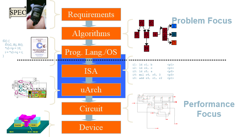
- The Big Picture
- CPU Basics
- Clocks
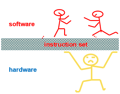
- ISA (Instruction Set Architecture)
- uArch
The article is converted from a PPT which was written by me in 2013 used to train our team software engineers.
The Big Picture
CPU Basics
-
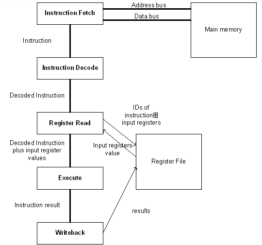
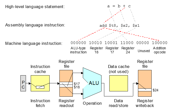
The computer’s CPU fetches, decodes, and executes program instructions.
-
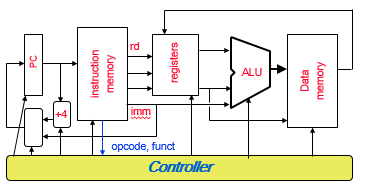
The two principal parts of the CPU are the datapath and the control unit.
- The datapath consists of an arithmetic-logic unit and storage units (registers) that are interconnected by a data bus that is also connected to main memory.
- Various CPU components perform sequenced operations according to signals provided by its control unit.
- The control unit determines which actions to carry out according to the values in a program counter register and a status register.
Clocks
-
Every computer contains at least one clock that synchronizes the activities of its components.
-
A fixed number of clock cycles are required to carry out each data movement or computational operation.
-
The clock frequency, measured in megahertz or gigahertz, determines the speed with which all operations are carried out.
- Typical Intel and typical PIC clocks look like this:
- 2 GHz clock has a cycle time of 0.5 nanoseconds.
- 8 MHz clock has a cycle time of 0.125 microseconds.
- One master clock has multiple frequencies used for various parts of the system.
ISA (Instruction Set Architecture)
-
Instruction Set Architecture is the structure of a computer that a machine language programmer (or a compiler) must understand to write a correct (timing independent) program for that machine.
-
ISA is the set of all instructions that the microprocessor can execute
- The set of instructions executed by a modern processor may include:
- Data transfer instructions
- data movement (load, store, push, pop, move, swap - registers)
- Data operation instructions
- arithmetic and logical (negate, extend, add, subtract, multiply, divide, and, or, shift)
- Program control instructions
- control transfer (jump, call, trap - jump into the operating system, return - from call or trap, conditional branch)
- Data transfer instructions
Instruction Processing
- The datapath based on data transfers required to perform instructions
- A controller causes the right transfers to happen
Instruction Execution
Instruction Formats
In designing an instruction set, consideration is given to:
- Instruction length.
- Whether short, long, or variable.
- Number of operands.
- Number of addressable registers.
- Memory organization.
- Whether byte - or word addressable.
- Addressing modes.
- Choose any or all: direct, indirect or indexed
Addressing Modes
Instructions can specify many different ways to obtain their data
- data in instruction
- data in register
- address of data in instruction
- address of data in register
- address of data computed from two or more values contained in the instruction and/or registers
On a RISC machine, arithmetic/logic instructions use only the first two of these ADDRESSING MODES
On a CISC machine, all addressing modes are generally available to all instructions
RISC vs. CISC
-
The believe that better performance would be obtained by reducing the number of instruction required to implement a program, lead to design of processors with very complex instructions (CISC)
CISC – Complex Instruction Set Computers
-
As compiler technologies improved, researchers started to wonder if CISC architectures really delivered better performances than architectures with simpler instruction set
RISC – Reduced Instruction Set Computers
-
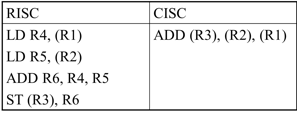
Addition of two operands from memory, with result written in memory, in RISC and CISC architectures
- Having an operation broken into small instructions (RISC) allows the compiler to optimize the code
i.e. between the two LD instructions (memory is slow) the compiler can add some instructions that don’t need memory access
- The CISC instruction has no option but to wait for its operands to come from the memory, potentially delaying other instructions
RISC Characteristics
- One instruction per cycle
- Register to register operations
- Few, simple addressing modes
- Few, simple instruction formats
- Hardwired design (no microcode)
- Fixed instruction format
- More compile time/effort
Architecture Implementation
uArch
Pipelining
What Is Pipelining
- Pipelining doesn’t help latency of single task, it helps throughput of entire workload
- Pipeline rate limited by slowest pipeline stage
- Multiple tasks operating simultaneously
- Potential speedup = Number pipe stages
- Unbalanced lengths of pipe stages reduces speedup
- Time to “fill” pipeline and time to “drain” it reduces speedup
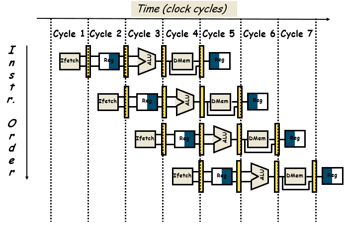
Instruction-Level Pipelining
- For every clock cycle, one small step is carried out, and the stages are overlapped.
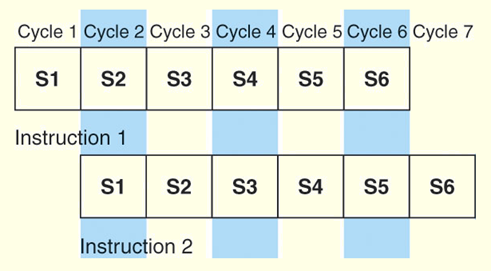
- S1. Fetch instruction.
- S2. Decode opcode.
- S3. Calculate effective address of operands.
- S4. Fetch operands.
- S5. Execute.
- S6. Store result.
The Five Stages of Load
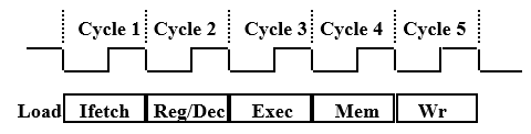
- Ifetch: Instruction Fetch
- Fetch the instruction from the Instruction Memory
- Reg/Dec: Registers Fetch and Instruction Decode
- Exec: Calculate the memory address
- Mem: Read the data from the Data Memory
- Wr: Write the data back to the register file
Pipeline Hurdles
Limits to pipelining: Hazards prevent next instruction from executing during its designated clock cycle.
Structural hazards: HW cannot support this combination of instructions- two different instructions use same h/w in same cycle
Data hazards: Instruction depends on result of prior instruction still in the pipeline- two different instructions use same storage
- must appear as if the instructions execute in correct order
Control hazards: Pipelining of branches & other instructions that change the PC- one instruction affects which instruction is next
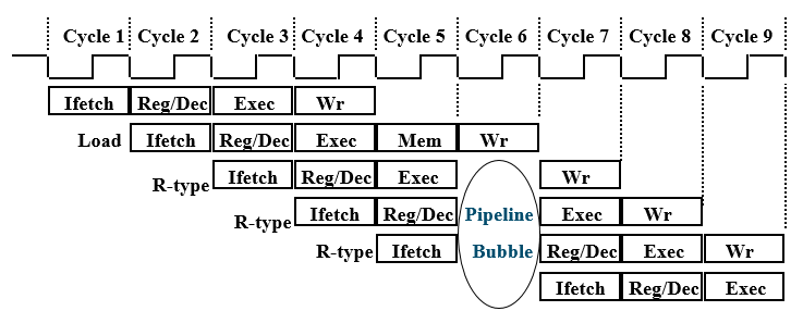
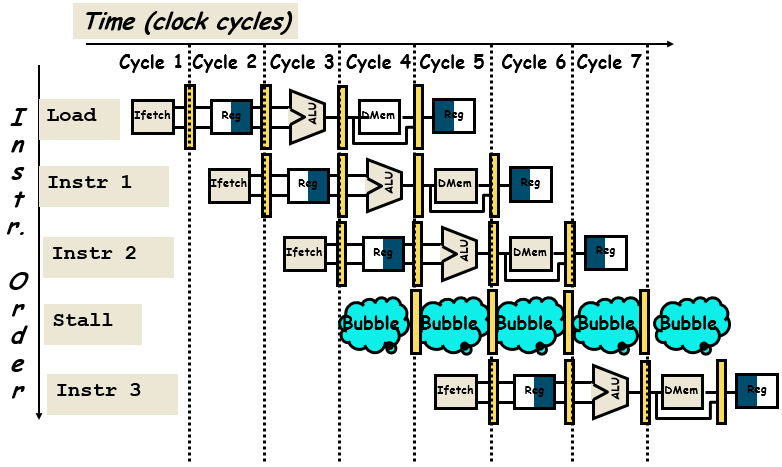
- Common solution is to stall the pipeline until the hazard is resolved, inserting one or more “bubbles” in the pipeline
Insert “Bubble” into the Pipeline
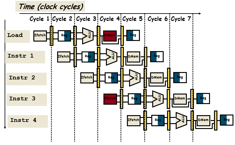
Data hazards
Predict Branch
- Advantages
- The main purpose of predication is to avoid jumps over very small sections of program code, increasing the effectiveness of pipelined execution and avoiding problems with the cache.
- Disadvantages
- Predication’s primary drawback is in increased encoding space.
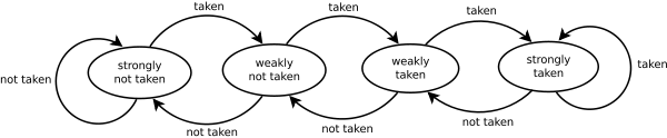
- 1-bit Prediction
- 2-bit Prediction
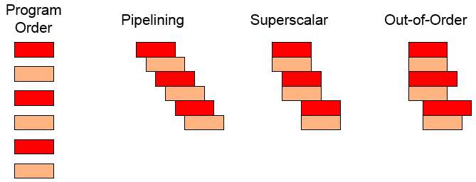
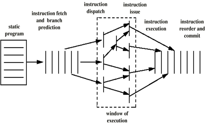
Out-of-order execution
Processor executes instructions in an order governed by the availability of input data, rather than by their original order in a program
Register renaming
Parallelism
- Instruction Level Parallelism
- Superscalar
- VLIW
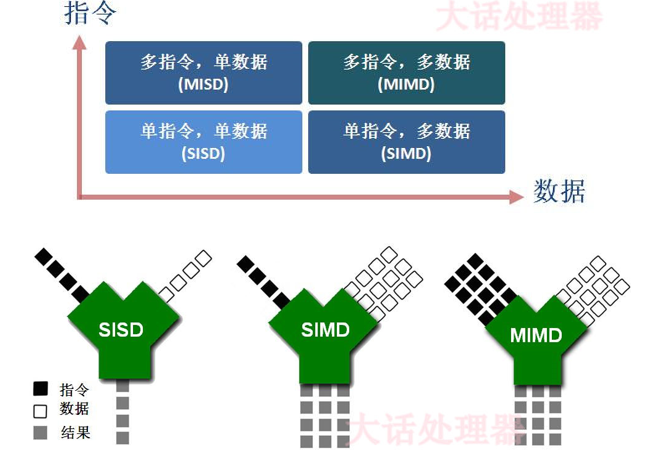
- Data Level Parallelism
- SIMD (Single Instruction Multiple Data)
- MMX
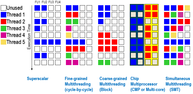
- Thread Level Parallelism
- Multithreading
- Multicore
- Multiprocessor
Superscalar
- Common instructions (arithmetic, load/store, conditional branch) can be initiated and executed independently
- Improve these operations by executing them concurrently in multiple pipelines
- Requires multiple functional units
- Requires re-arrangement of instructions
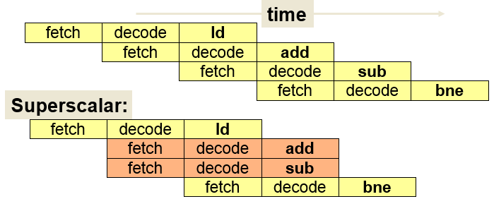
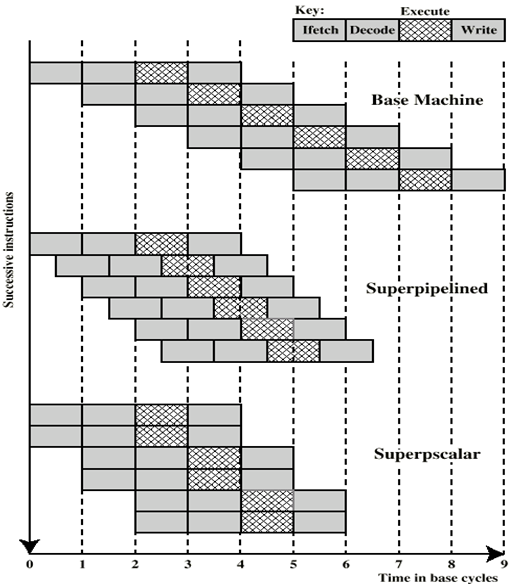
Superscalar Execution
Superpipelined
- Many pipeline stages need less than half a clock cycle
- Double internal clock speed gets two tasks per external clock cycle
VLIW - Very long instruction word
- Why
- To overcome the difficulty of finding parallelism in machine-level object code.
- In a VLIW processor, multiple instructions are packed together and issued in parallel to an equal number of execution units.
- The compiler (not the processor) checks that there are only independent instructions executed in parallel.
- characteristics
- VLIW contains multiple primitive instructions that can be executed in parallel by functional units of a processor.
- The compiler packs a number of primitive, non-interdependent instructions into a very long instruction word
- Since multiple instructions are packed in one instruction word, the instruction words are much larger than CISC and RISC’s.
Multithreading
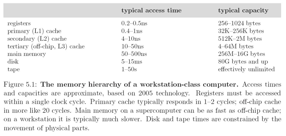
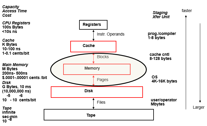
Cache
- The goal of a cache in computing is to keep the expensive CPU as busy as possible by minimizing the wait for reads and writes to slower memory.
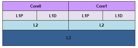
Memory Hierarchy
Cache
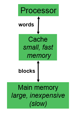
- Processor does all memory operations with cache.
Miss– If requested word is not in cache, a block of words containing the requested word is brought to cache, and then the processor request is completed.Hit– If the requested word is in cache, read or write operation is performed directly in cache, without accessing main memory.Block– minimum amount of data transferred between cache and main memory.
Cache Design
The level’s design is described by four behaviors:
- Block Placement:
- Where could a new block be placed in the given level?
- Block Identification:
- How is a existing block found, if it is in the level?
- Block Replacement:
- Which existing block should be replaced, if necessary?
- Write Strategy:
- How are writes to the block handled?
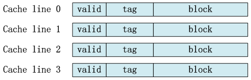
Cache Line
Three Major Placement Schemes
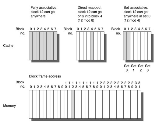
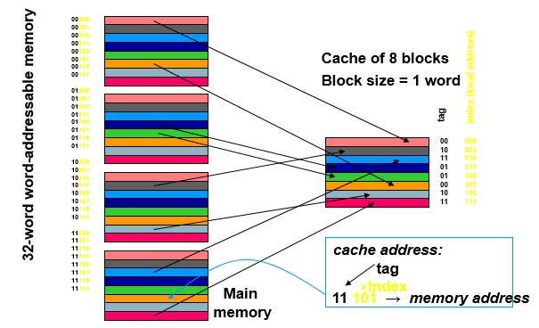
Direct-Mapped Cache
Two-Way Set-Associative Cache
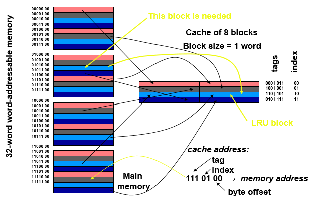
Replacement Strategies
-
Which existing block do we replace, when a new block comes in?
- With a direct-mapped cache:
- There’s only one choice! (Same as placement)
- With a (fully- or set-) associative cache:
- If any “way” in the set is empty, pick one of those
- Otherwise, there are many possible strategies:
- Random: Simple, fast, and fairly effective
- FIFO
- Least-Recently Used (LRU)
Writing to Memory
- Cache and memory become inconsistent when data is written into cache, but not to memory – the cache coherence problem.
- Strategies to handle inconsistent data:
- Write-through
-Write to memory and cache simultaneously always.
- Write to memory is ~100 times slower than to (L1) cache.
- Write-back
- Write to cache and mark block as “dirty”.
- Write to memory occurs later, when dirty block is cast-out from the cache to make room for another block
- Write-through
-Write to memory and cache simultaneously always.
Cache Coherence
- Also, before a DMA transfer, need to determine if information in main memory is up-to-date with information in cache. (write back protocol)
-
One solution is to always flush the cache by forcing the dirty data to be written back to memory before a DMA transfer takes place
- MESI